PricingCase Study
Log in
AOX Product

OPTIMIZATIONSAME LINES, MADE BETTER.

AOX reshapes your own geometry to cut drag or add downforce, only where and only as far as you allow. AOX finds the direction; designers decide how far.

Get started
HOW IT WORKS

Flow, sensitivity, shape. Repeat.

AOX alternates between computing the airflow and moving the surface, refining the shape a little every cycle.
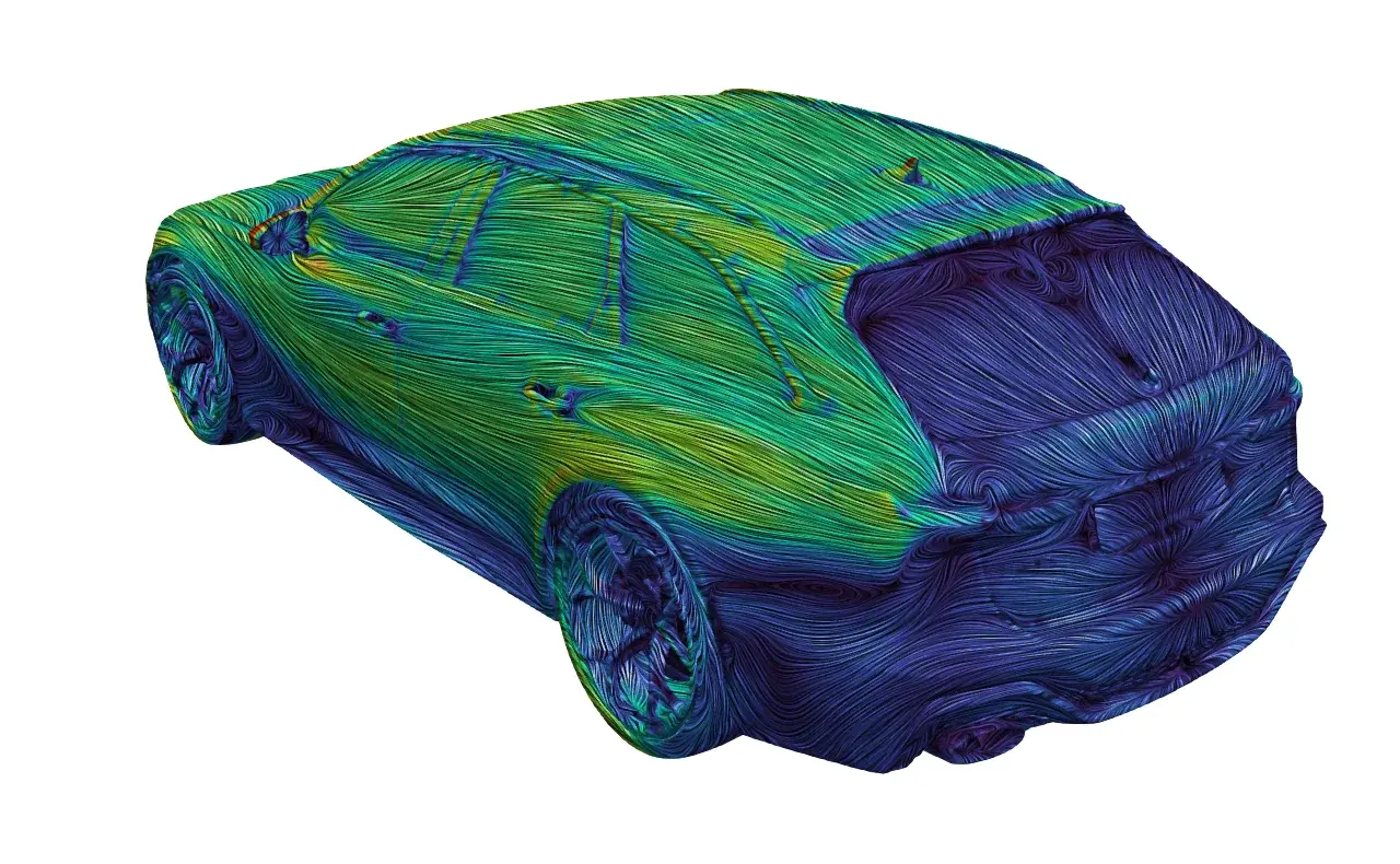
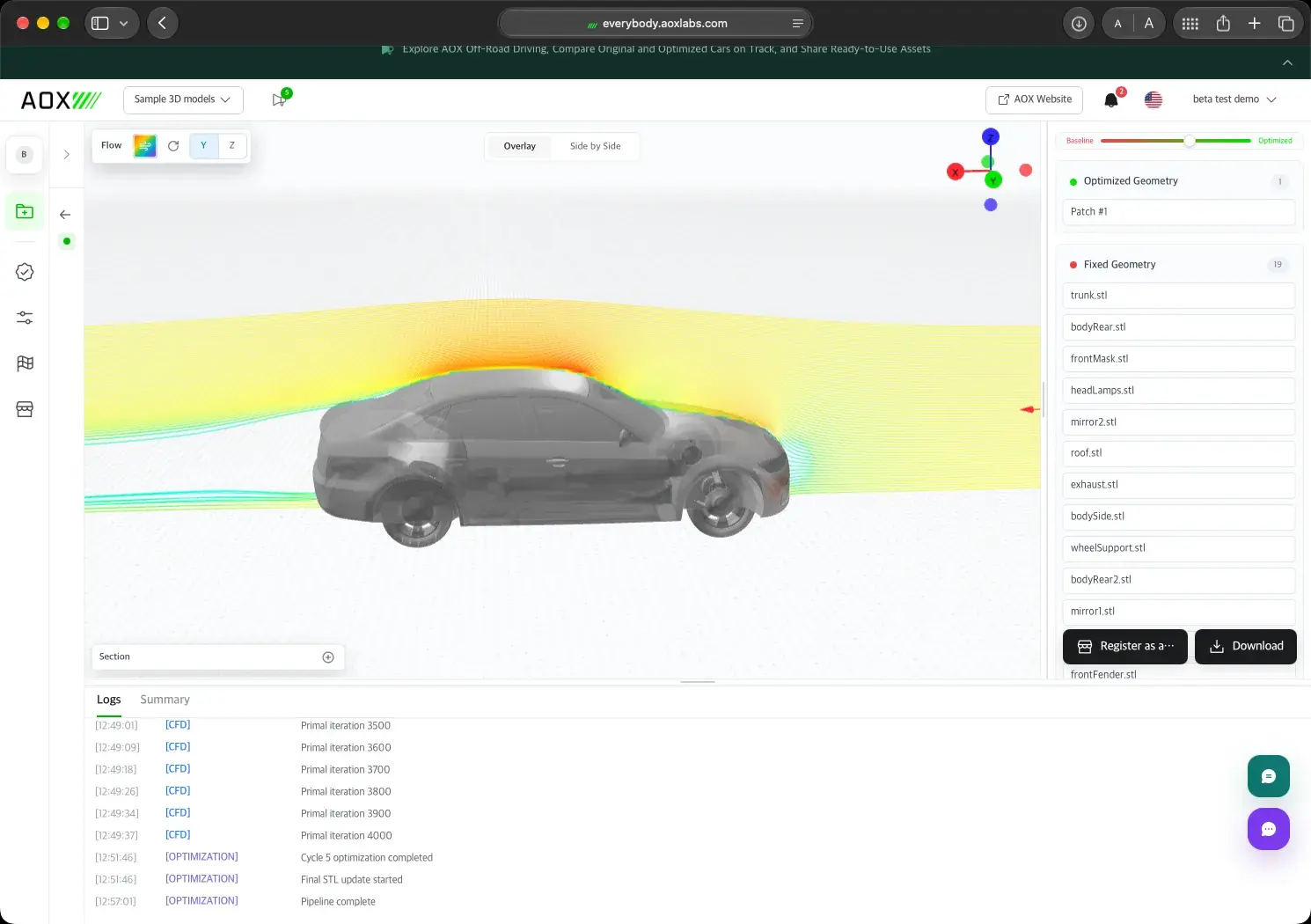
  1. Surface flow lines on an estate car coloured by air speed
    01

    Compute the flow

    The space around the shape is split into tiny cells, and the velocity and pressure in each cell give the drag and lift on the shape.
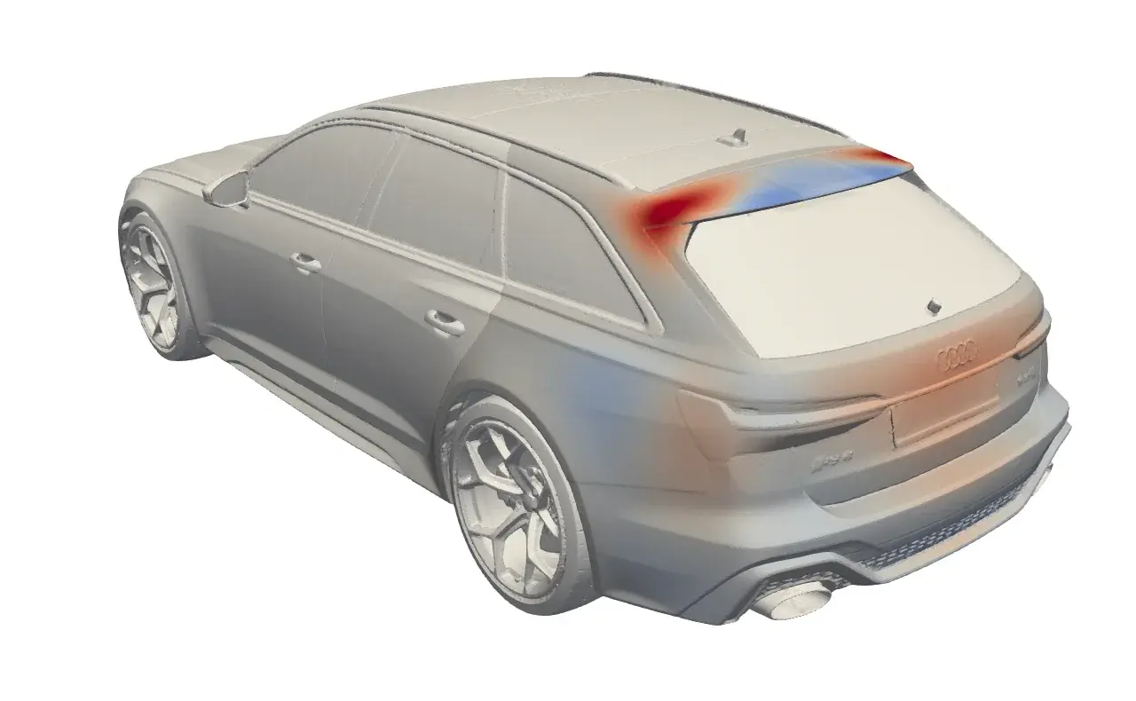
  2. Adjoint sensitivity map on the rear of an estate car, red and blue where moving the surface matters most
    02

    Find the sensitivity

    For every point on the surface at once, AOX works out which way to move it, and how far, to improve the goal.
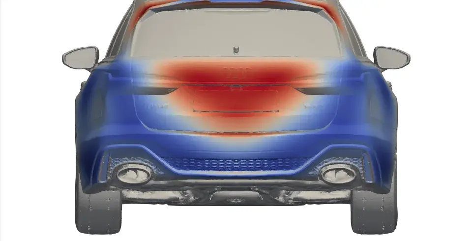
  3. Normal displacement on the rear of the car after five optimization cycles
    03

    Move the surface

    The surface moves a little along the sensitivity, inside your regions and limits, with its surroundings following smoothly.
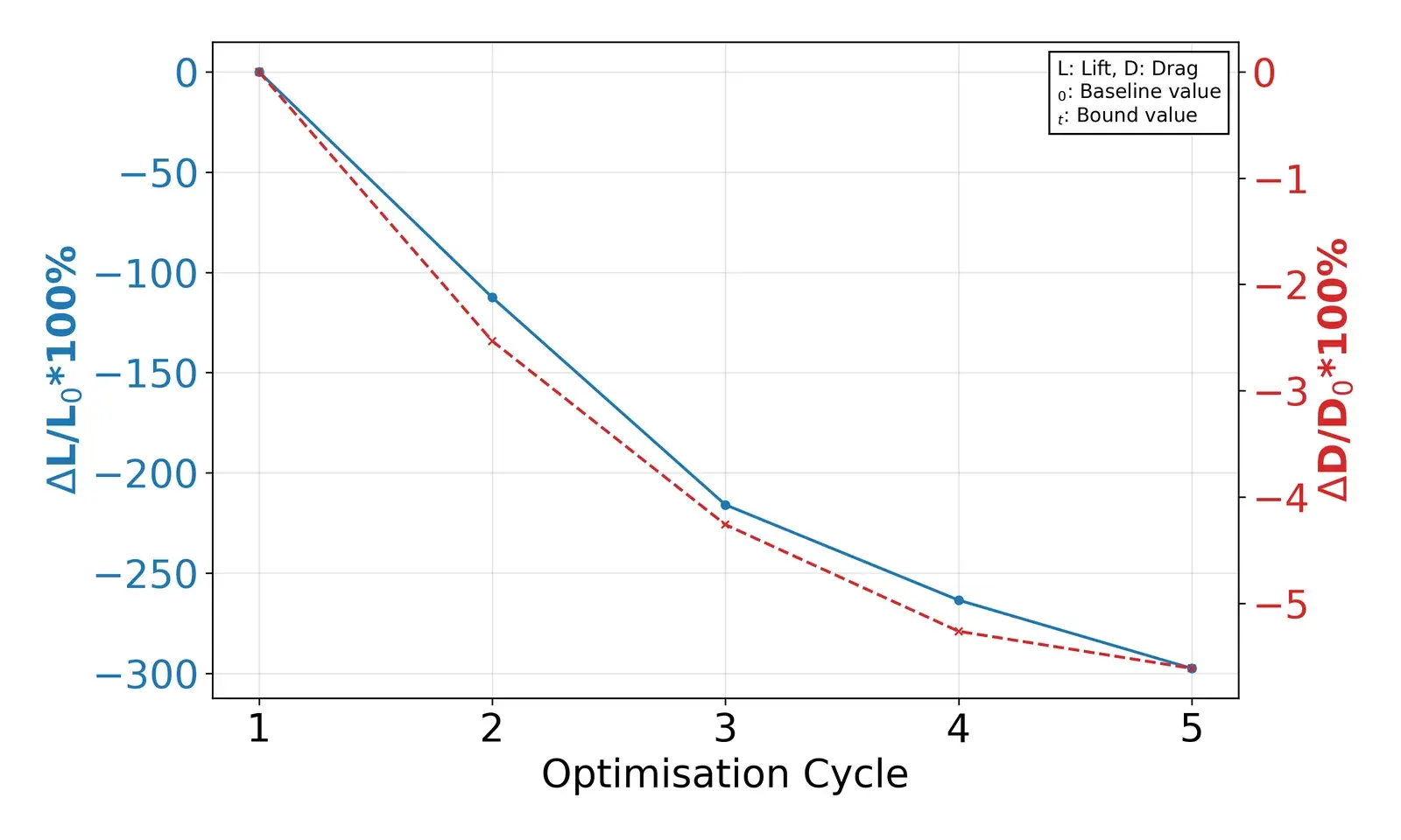
  4. Lift and drag falling over five optimization cycles
    04

    Repeat

    The new shape goes back to the flow step, for as many cycles as you set.

WHY ADJOINT

Every point, in one extra solve.

Most shape optimization builds candidate shapes and computes the flow for each of them. AOX uses the adjoint method instead.
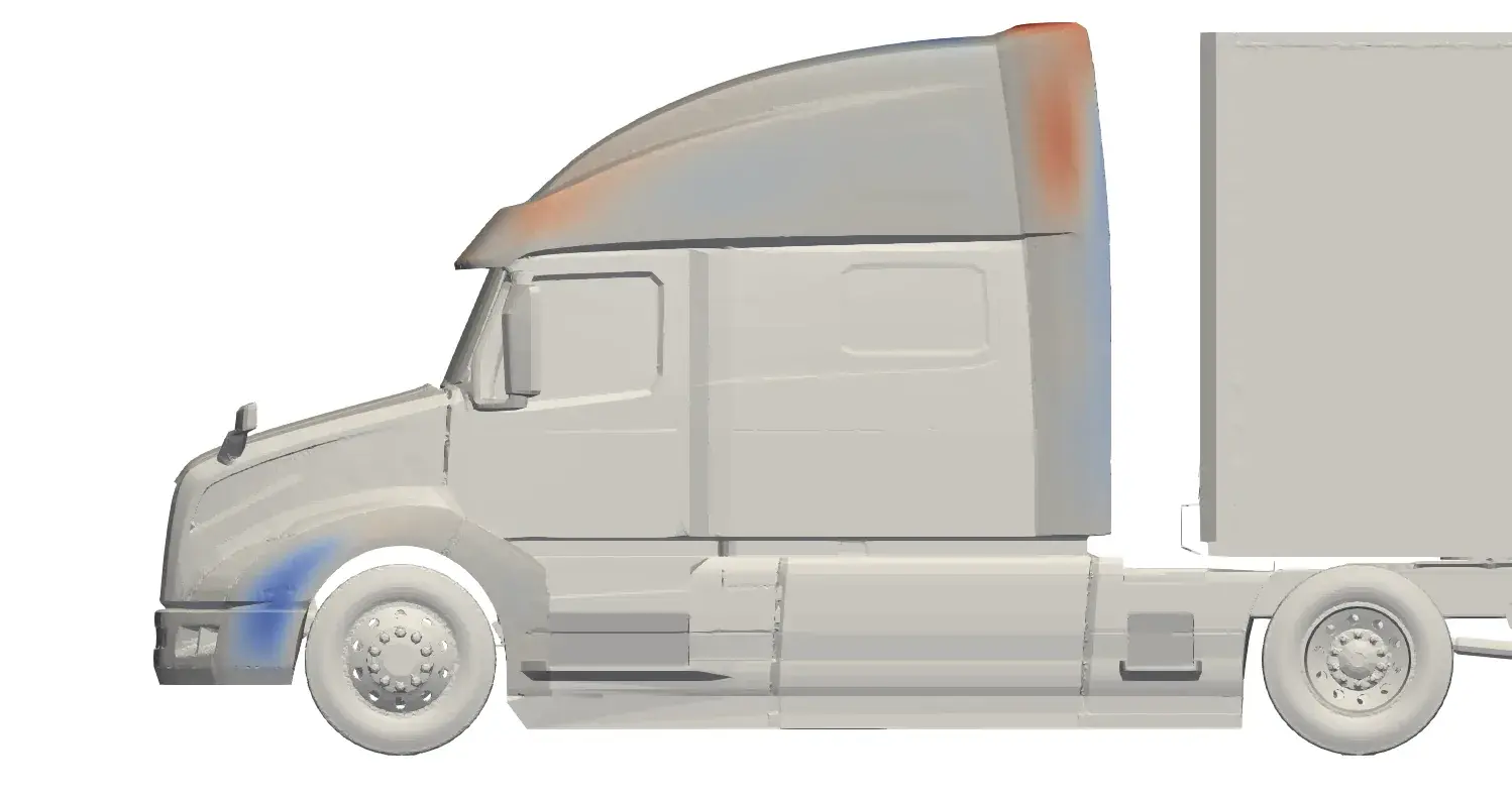
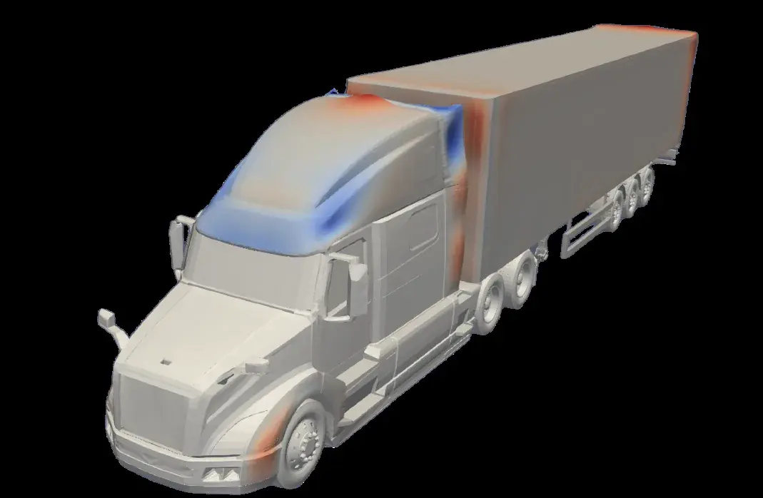
Adjoint sensitivity map on a truck cab, strongest at the roof fairing and the front corners
Candidate search

One flow solve per candidate

Make several candidate shapes, compute the airflow around each one, and keep the best.

  • The more areas you want to change, the more candidates you need
  • Every candidate costs a full flow solve
AOX

Adjoint sensitivity

After the flow solve, one more computation shows how every point on the surface should move, and how much the goal improves.

  • A sensitivity map, painted on the surface
  • The shape follows the map, cycle after cycle
SET UP IN SEVEN STEPS

From upload to run.

Bring the files as they are and skip the mesh. Recommended values are filled in along the way.

  1. 01

    Create a project

    Select New Project and give it a name.
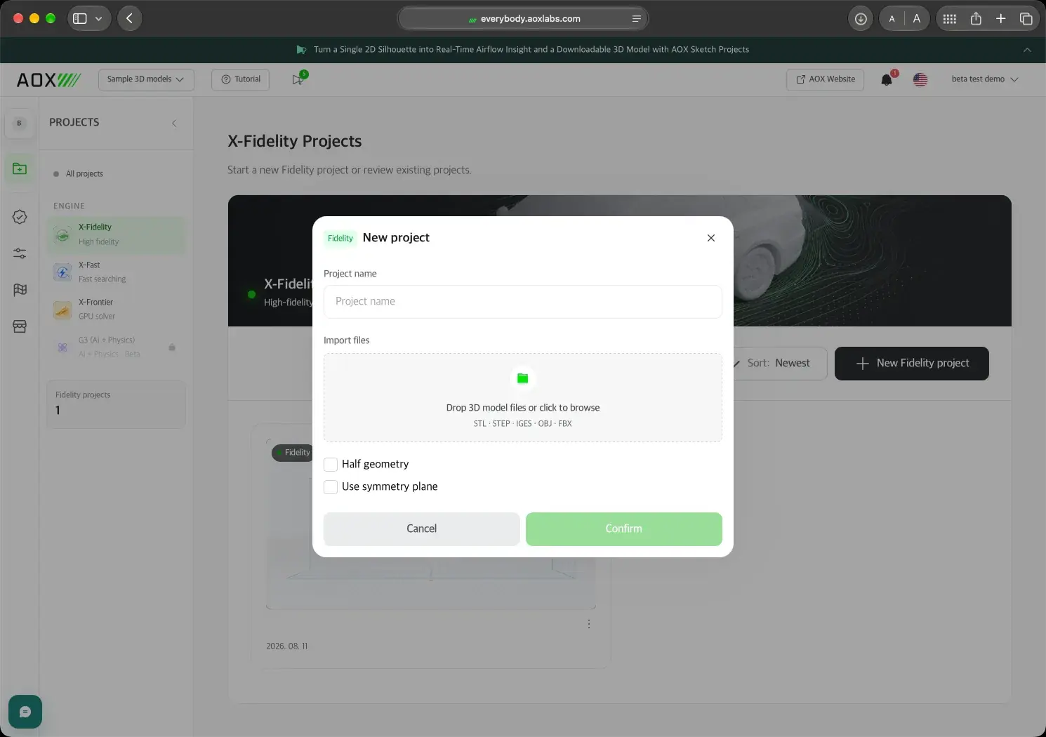
    New project dialog with the project name, file import, half geometry, and symmetry plane options
  2. 02

    Upload and check the shape

    Drop in one file, or several files split by part. Every upload is checked automatically to see whether the shape is fully closed.

    • STL (.stl, .stlb), STEP (.step, .stp), IGES (.iges, .igs), OBJ, and FBX
    • Repair (keep parts) fills small gaps and simple holes without changing the shape
    • Force watertight always closes the shape, but sharp character lines may round off and intended openings such as grilles may close
    • Half geometry for one side of a symmetric model, mirrored across the symmetry plane

    Both repairs are automatic and may not fix every shape. Checking the source file before upload gives the most accurate results.

    Imported part files with a watertight check suggesting review, and the Repair (keep parts) and Force watertight buttons
  3. 03

    See it in 3D

    The shape opens in 3D, with streamlines generated around it automatically.
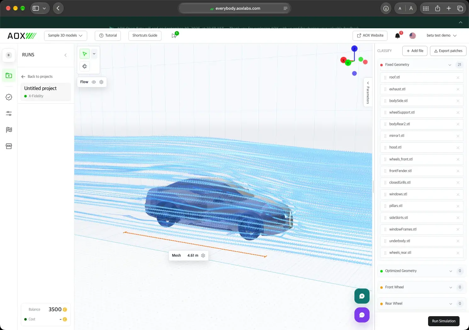
    • Turn the streamlines on or off and change the flow speed
    Uploaded car in the workbench with streamlines around it and its 4.61 m length shown
  4. 04

    Choose what may change

    Paint the regions to optimize right on the model. Selections run smoothly across part boundaries.
    • Brush paints detail, with an adjustable brush size
    • Lasso encloses a large area at once
    • New, add, and remove selection modes
    • Or move whole parts into the optimized set
    Rear of a sports car with the region to optimize painted on the surface
  5. 05

    Set the wheels

    For a car, mark the front and rear wheels. They turn at road speed over a moving road, for results closer to real driving.
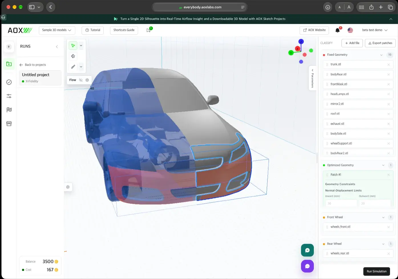
    • Available when the wheels are uploaded as separate files
    • Without wheels, set the height above the ground instead
    Parts sorted into fixed geometry, optimized geometry, front wheel, and rear wheel, with the optimized region highlighted
  6. 06

    Limit the deformation

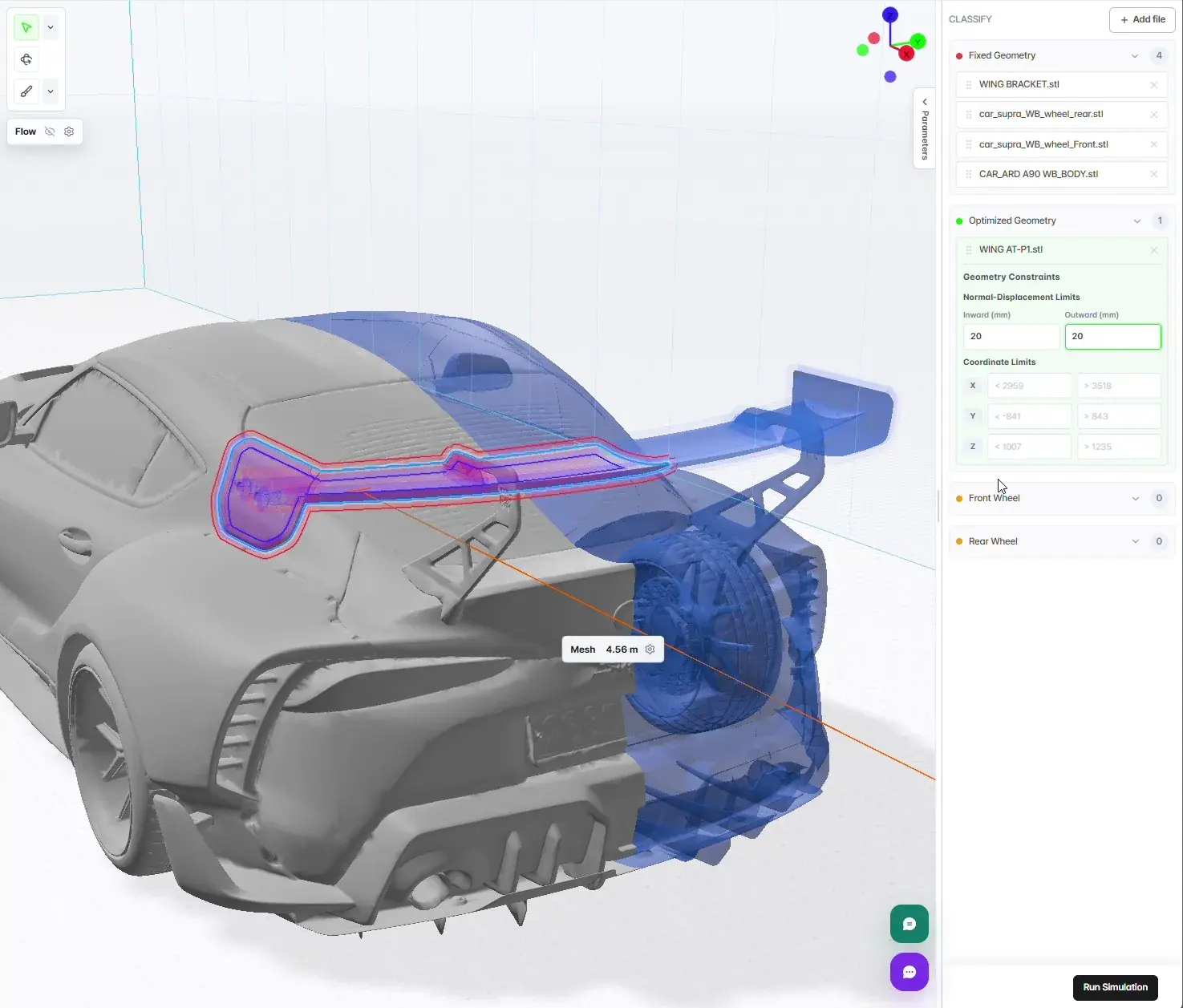
    Set how far, and in which direction, the optimized regions may move. These limits protect the design intent and production constraints.

    • Normal-displacement limits: how far the surface may move inward and outward
    • Coordinate limits: minimum and maximum positions on X, Y, and Z, for example keeping a front lip at least 160 mm above the ground
    • Or an offset from the baseline shape

    Even when the shape should only grow outward, leave about 2 mm of inward room. With no room at all, the optimization may not progress.
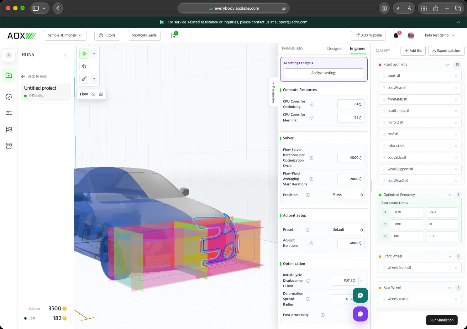
    Coordinate limit planes around the front of a car, with Engineer mode settings in the side panel
  7. 07

    Set the parameters

    Choose Designer mode for the goal and the essentials, or Engineer mode for mesh, solver, and compute settings.

    • AI settings analysis reviews the setup and suggests better-suited values

    AI suggestions are a reference, not a rule.
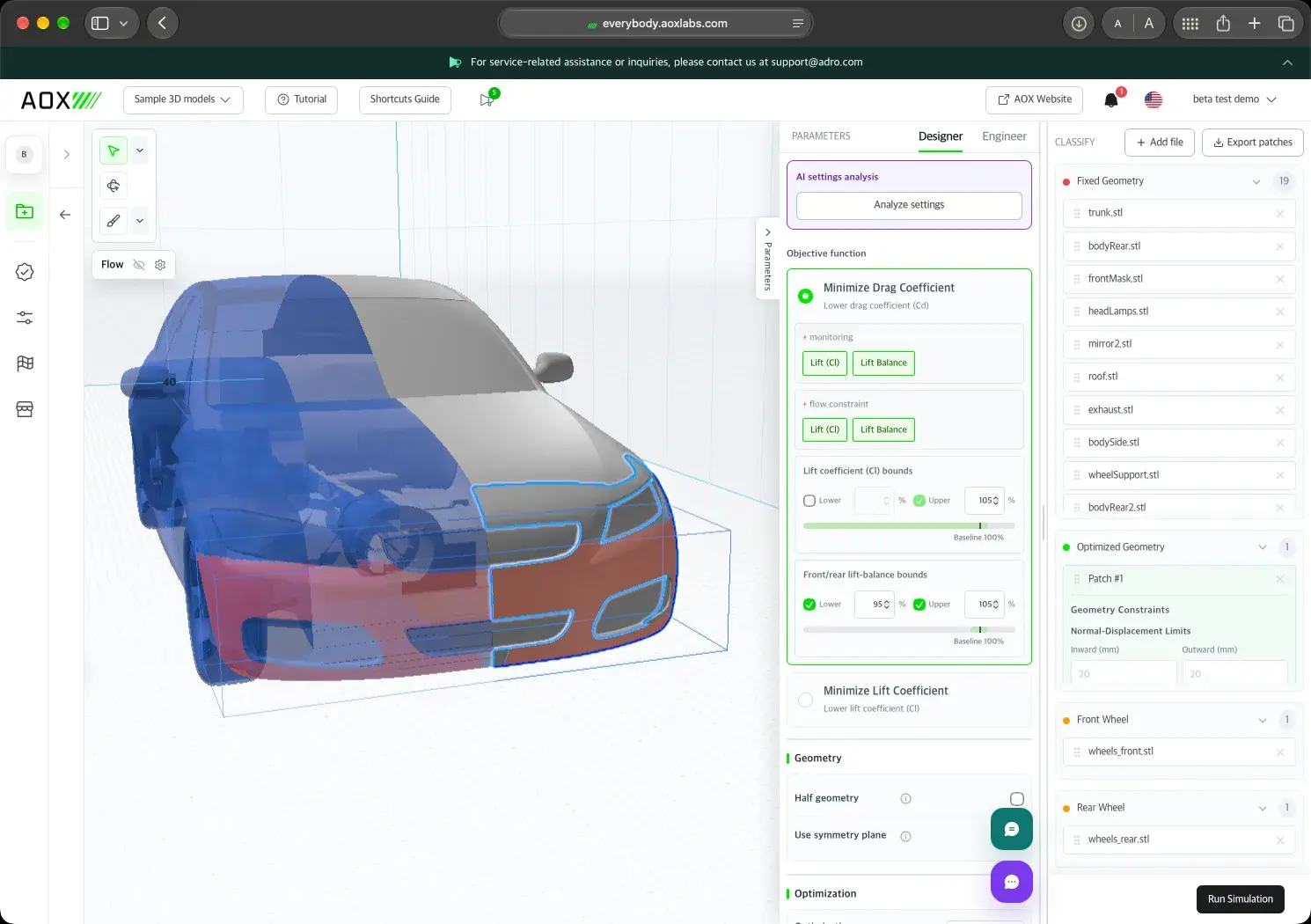
    Designer mode with AI settings analysis and the minimize drag objective with monitoring and bounds
GOALS

Lower drag. Or more downforce.

Pick one objective. Then watch other values, or keep them inside a range while AOX optimizes.

Objective

Minimize drag coefficient (Cd)

Lower air resistance for better fuel or energy efficiency and a higher top speed.

  • Monitor lift (Cl) to check that downforce does not drop
  • Monitor or bound lift and lift balance
Objective

Minimize lift coefficient (Cl)

Less lift means more downforce, for stability at high speed.

  • Monitor drag (Cd) to see how much air resistance rises
  • Monitor or bound drag and lift balance

Monitoring only records a value and does not change the result. A flow constraint keeps a value between lower and upper bounds, set as a share of the baseline shape (100%). Each added constraint needs one more computation, which adds time and credits.

RUN

Hands off. Get back to designing.

Once you start the run, AOX takes it from there.

  1. 01

    Meshed for you

    The mesh is built automatically. There is nothing to set.

  2. 02

    Runs on its own

    Cycle after cycle with no input needed. Live flow and logs are there whenever you check in.

  3. 03

    Done

    The optimized shape is ready to review and download.

Credits are shown before every run.
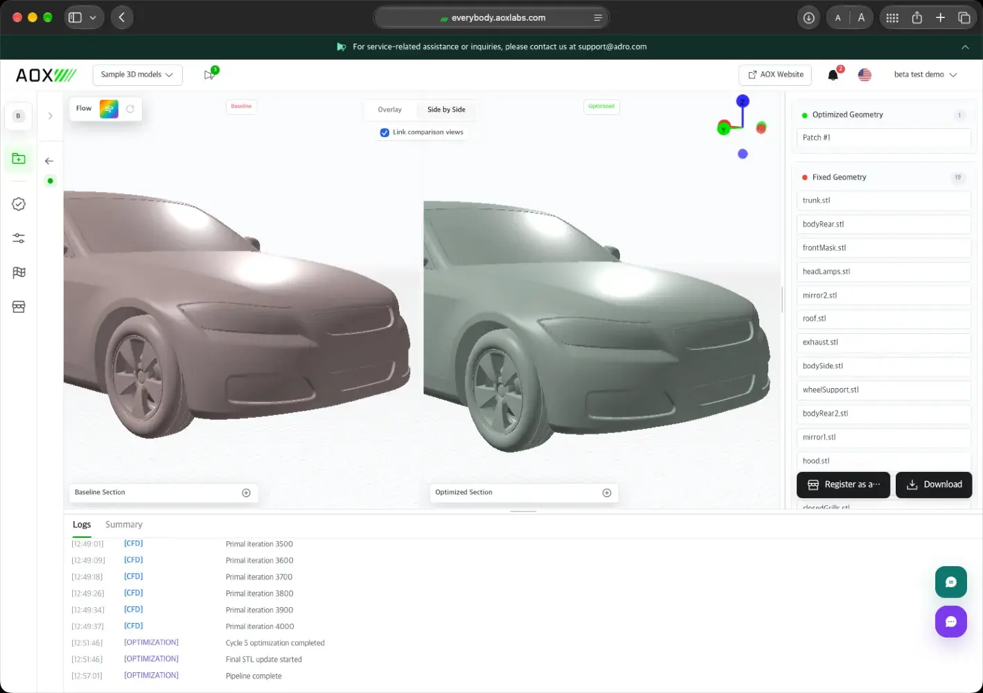
REVIEW

See what changed. From every angle.

Baseline and optimized cars side by side in the result viewer
Side by side — baseline and optimized, with linked cameras.
Velocity-coloured flow on a section plane around the optimized car
Flow and section — velocity-coloured flow on any plane, with slices for subtle changes.
REPORT

The shape, and the numbers behind it.

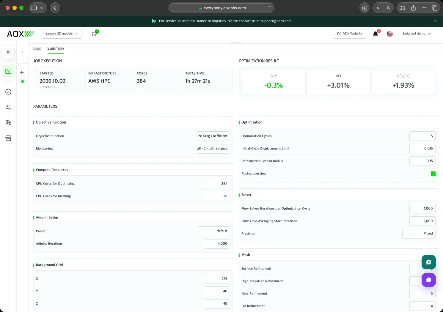
Run summary with the change in drag, lift, and lift-to-drag ratio and the full parameter list
Result at a glance — ΔCd, ΔCl, and Δ(Cl/Cd) against the baseline, with every parameter, runtime, and compute resource saved.
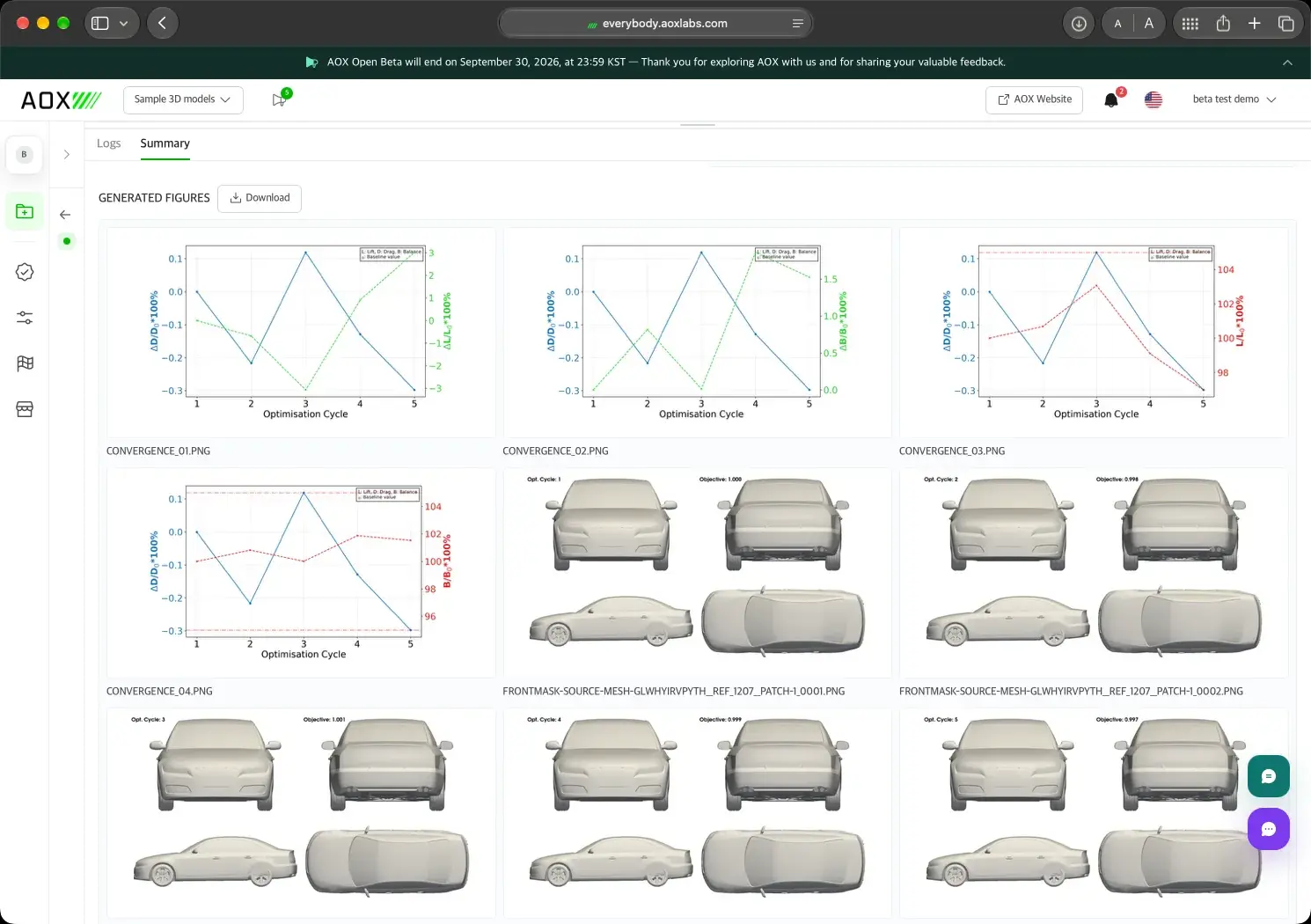
Generated figures with convergence charts and shape snapshots for each cycle
Every cycle traced — convergence charts and a shape snapshot for each cycle.

Download the baseline or optimized geometry, plus every figure.
CASE STUDIES

Proven on real projects.

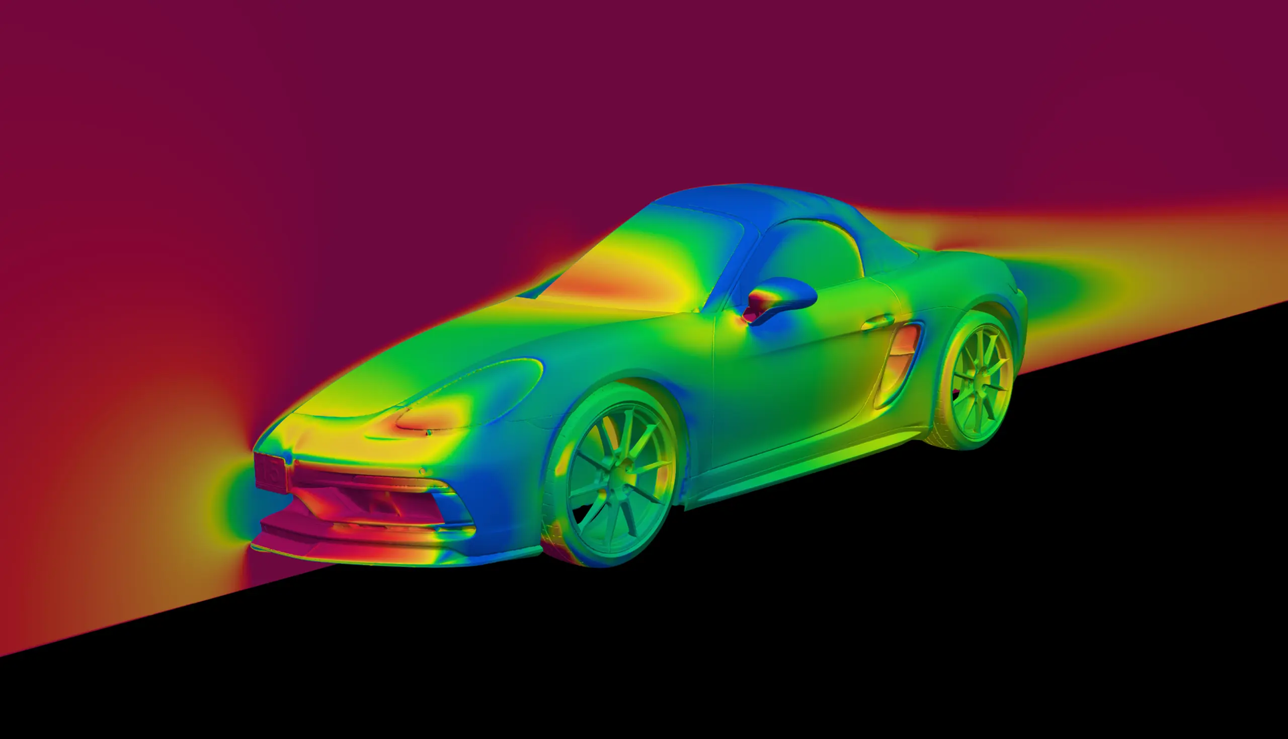
Porsche 992.1 GT3 with AOX-optimized aero parts

Porsche 992.1 GT3

Downforce-oriented front splitter and rear wing

Total downforce
+132%
Total drag
+28%
Downforce-to-drag ratio
+81%

Compared with the stock car. Starting geometry: ADRO aero kits.
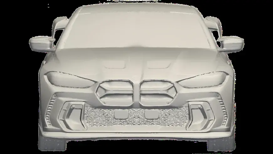
Front of a BMW M4 with ADRO aero parts

BMW M4 aero parts by ADRO

Human-designed, AI-refined front splitter and rear wing

Total downforce
+24%
Total drag
+13%
Downforce-to-drag ratio
+9.8%

Compared with ADRO's original design.

Class 8 truck with the optimized sectors coloured on the cab and container

Class 8 long-haul truck

Drag-oriented cab roof, fender, rear cab, and container

Total drag
−7.4%
Fuel efficiency
+3.4%

Fuel efficiency estimated with the VECTO model and ICCT reports.

DESIGNER AND ENGINEER MODES

Simple when you want it. Deep when you need it.

Designer mode asks only for the goal and the essentials and applies verified defaults to the rest. Engineer mode opens every setting below.

Designer mode

Objective
Minimize Cd or Cl, with monitoring and flow constraints
Geometry
Half geometry and symmetry plane
Optimization cycles
5 to 10 recommended

Compute resources

CPU cores for optimizing
384 (up to 384)
CPU cores for meshing
128 (up to 128)

Solver

Flow iterations per cycle
4,000
Averaging starts at iteration
2,000
Precision
Mixed, or Double

Adjoint setup

Preset
Default, Balanced, or Conservative
Adjoint iterations per cycle
4,000

Optimization

Initial-cycle displacement limit
15 mm
Deformation spread radius
150 mm
Proximity radius
150 mm
Post-processing
Shape images and convergence graphs every cycle

Background grid and flow

Grid cells X / Y / Z
278 / 40 / 40
Freestream velocity
30 m/s (about 108 km/h)

Mesh

Surface refinement
6
High-curvature refinement
6
Near refinement (within 0.1 m)
5
Far refinement (within 0.3 m)
4
Main layers
5
Wheel layers
5
Wheel expansion ratio
1.6
Wheel final thickness
0.8

These defaults are verified in AOX. Radius and displacement values are tuned for a typical car, so adjust them when your shape is much smaller or larger.

INSIDE ONE CYCLE

What every setting controls.

Each Engineer setting tunes one stage of the cycle.

  1. 01

    Mesh

    The space around the shape is split into cells. The mesh deforms with the shape and is rebuilt automatically when its cells distort too much.

    Background grid · Mesh · CPU cores for meshing

  2. 02

    Flow

    The airflow around the current shape and the goal value, such as drag or lift, are computed.

    Flow iterations · Averaging start · Precision

  3. 03

    Sensitivity

    AOX computes how the goal changes when each point on the surface moves. Each flow constraint adds one more of these computations.

    Adjoint preset · Adjoint iterations

  4. 04

    Deformation

    The surface moves along the sensitivity map, stays smooth, blends into fixed areas, and keeps inside your limits. The first cycle moves only a little.

    Spread radius · Proximity radius · Limits · Initial-cycle limit

The improvement gets smaller with each cycle until it converges. The optimization mesh is lighter than a single precise analysis so it can cycle quickly, so read the result as the direction of improvement against the baseline and treat absolute forces as a reference.

AERODYNAMICS, IN PLAIN WORDS

Read the results with confidence.

The ideas behind every AOX setting and result.

Pressure
Air presses hard where it hits the front of a shape and less where it speeds up around it. These differences add up to drag and lift.
Boundary layer
A layer of air a few millimetres thick clings to the surface and speeds up sharply away from it. Skin friction and separation are both decided here.The layer settings in Engineer mode resolve this region.
Separation
Air follows gentle curves but breaks away where the shape turns sharply or ends, such as a roof edge, the end of the trunk, or a bumper corner.
Wake
Separated air leaves a low-pressure region of vortices behind the shape. High pressure in front and low pressure behind make pressure drag, most of a passenger car’s drag.Drag optimization usually delays separation and shrinks the wake. You can see the flow tidy up in the streamlines.
Lift and downforce
Pressure differences above and below a moving shape create a vertical force: lift when it raises the shape, downforce when it presses it down. More downforce means more grip at speed, usually with more drag.Lift (Cl) is the size of this force, and lift balance is how it splits between front and rear.
Coefficients
Cd and Cl divide the force by the speed and the size of the shape, so different cars and speeds can be compared directly.
UNDER THE HOOD

Two engines, each built for its job.

Fast enough for every iteration.

Optimization engine

Adjoint CFD on HPC

One extra solve shows how every surface point pushes drag or lift.

  • Node-level shape control: each surface node moves on its own, inside your limits, so changes stay smooth
  • A mesh that keeps up: integrated meshing refines the surface through every loop
  • Example run: 384 cores, 5 cycles in 1 h 27 min
Validation engine

Lattice Boltzmann LES on GPU

No body-fitted mesh: the grid builds and refines itself where the flow needs it.

  • Wall-modelled LES handles the thin surface layer, so a whole car fits on one GPU
  • Custom GPU kernels give the same answer 5.6 × faster than our first build
  • 187 million cells on one GPU; a car-body LES in 73 minutes, down from 409
OPTIMIZE, THEN VALIDATE

Two steps to a final number.

Explore candidate shapes with optimization, then compare them or confirm the final one with an LES validation in Lab.

OptimizationValidation (LES)
Use it toFind a design directionCompare candidates or confirm final values
What it doesReshapes the geometry toward your goalMeasures the forces on the shape as it is
You getThe improved direction and the reshaped geometryAbsolute Cd and Cl, forces in N, flow images and videos
TimeMinutes to over an hour, by size and settingsAbout 15 minutes to 3 hours, by grade
MORE IN AOX

Keep exploring.

  • Design

    From a sketch to a 3D model

  • Geometry

    Clean, convert, align, and lighten models

  • Lab

    Simulators and experiments

LET YOUR NEXT DESIGN TAKE SHAPE

Your next design.
Your move.

Get started

Product

OptimizationDesignGeometryLabPricing

Resources

Case StudyBoard

Company

AboutContact

Service policies

Privacy PolicyTerms of ServiceRefund Policy
AOX

Aero for everyone.

Phone+82-31-338-1151
Emailsupport@aoxlabs.com
ADRO Inc. · Representative: Seunghyun Yoon · Business Registration No. 827-87-01633
100-29, Songju-ro 236beon-gil, Yangji-myeon, Cheoin-gu, Yongin-si, Gyeonggi-do 17159, Republic of Korea
Copyright © 2026 ADRO Inc. All rights reserved.
AOX

Aero for everyone.

ADRO